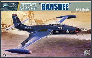
Manufacturer: KittyHawk Models
Stock Number: KHM 80131
Scale: 1/48
Most of the time when I build a model, I will spend some time reading build reports for the particular kit. Though every modeler’s experience differs somewhat, these reports can help identify potential problem areas, or just simply ways of making the build simpler.
When I read up on KittyHawk’s Banshee kit, the best I could find was that it was a difficult but achievable build. And the thoughts on KittyHawk kits in general often bordered on the obscene.
Still, I was intrigued enough by the Banshee itself to want to give it a shot.
So I gathered all the information I could, and found that the majority of the problems/complaints centered around the nose gear, the air inlets, and the wing fold area when modeling the wings fully extended. Based on information from other’s builds, and after thoroughly examining the parts and instructions, I came up with some plans to address each of those areas.
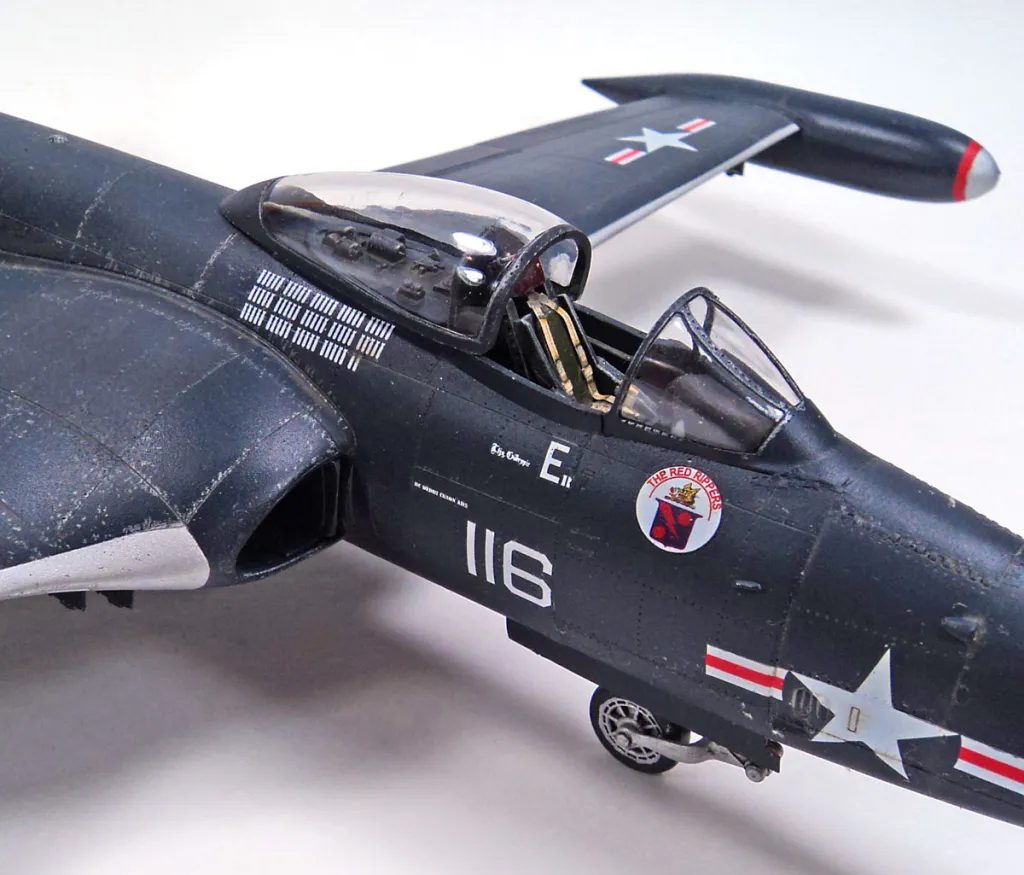
I started with the cockpit, which is a nicely detailed assembly. It’s not the best you’ll find, but it’s no slouch either. Except for a set of Eduard seat belts, I went ahead and built it right out of the box. Test fitting into the forward fuselage half showed no problems with fit.
Next up I tackled the nose gear assembly and gear bay. I’d read in several places that the nose gear had no positive attachment points, and that it was over engineered. Now I’ll admit it has more than a few pieces. However, the Banshee’s nose gear was not a simple vertical strut. It was designed to allow the strut to be lowered- essentially letting the airplane “kneel” down, raising the tail up, and allowing more aircraft to be parked in a carrier deck. So the way KittyHawk designed it is very realistic- and probably couldn’t be done in too different a fashion anyway to be able to capture the look of the part.
Additionally, I saw immediately that there are positive alignment points- four of them. On the sidewalls of the nose gear bay.
After test assembling the unit several times, I took a very radical but simple approach: I followed the instructions.
Of course, I had painted everything first, and added all the weathering. But assembling the full nose gear part (minus the nose wheel) first, and allowing it to fully dry, really helped. I placed the fore and aft nose bay parts on the “roof” portion of the bay, added one sidewall, positioned the piece of tubing that runs fore and aft, positioned one side of the nose gear into the slots designed for that purpose, positioned the other sidewall, and fully seated the nose gear in place. A few touches of glue and it was done.
To be honest, with this aspect of the build, I’m not sure why it presents a problem. If you follow the sequence, make sure your parts are aligned correctly, and not try to rush it all in one quick assembly session, it’s trouble free.
Test fitting this assembly into the nose, along with the cockpit, showed a perfect fit.
A final test fit of the fuselage showed that a reasonable approach would be to glue the forward halves together, with cockpit and nose gear in place, but leave the aft half unglued. (The aft cockpit decking can be left off until later if you prefer.) This allowed the arrestor hook “bay” to be slid into place from within the lower opening for the wing, properly positioned inside both halves, and then everything was glued. The fit of the fuselage halves was excellent, only some sanding of the seams was needed. I went ahead and glued the gun cover doors on to the forward nose parts at this point, and added those to the fuselage. With care to remove all flash and burrs, it was a perfect fit.
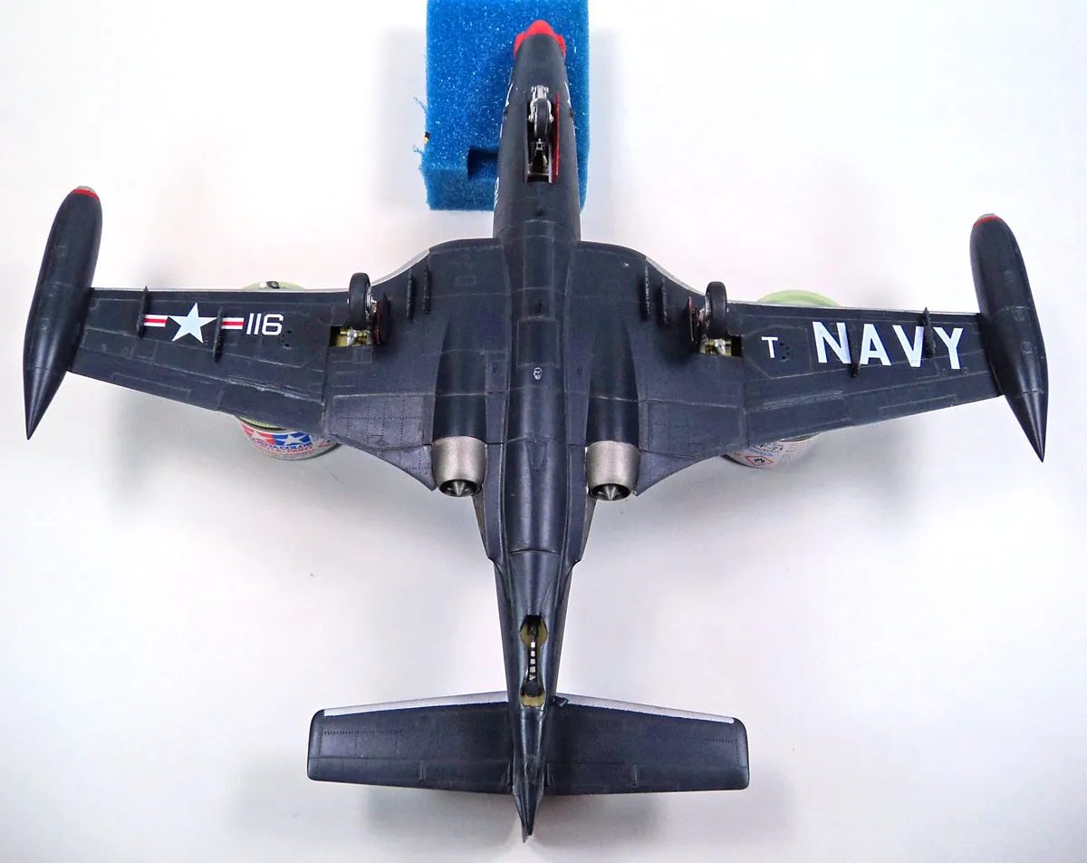
Next up were the engines and inner wing sections. The kit instructions would have you assemble the engines, add the air intakes to the front, and the exhaust nozzle to the rear, and then mount it inside the lower wing center section. The two upper sections are then set in place, and everything lines up- in theory. Test fitting of this sequence showed some alignment issues between the air intake parts on the engine faces, and the adjoining mating surfaces of the upper and lower wing.
Seeing that what mattered was the fit of the intakes to the wings, NOT the engines, I reversed the process. I tested fitting the engines to the lower wing without the intakes. The, I set the intake parts in, aligning them with the inner rim of the lower wing part, and then fitting the upper wing part.
It worked perfectly. Any misalignment had been transferred to to the join of the intakes with the engine face- which would not be visible, except to that annoying IPMS USA judge with the tiny, bright flashlight. 🙂
All parts were glued in place, a final fit was done for adjustments, and that dragon was counted in the “slayed” column.
Next, I turned to another area that had been identified as a problem area- joining the wings together in the extended position.
For the folded position, it’s easy enough- build the inner parts, the outer parts, attach the wing fold mechanism parts, and call it a day. But for the extended position, it’s not quite so easy.
The instructions would have you do a butt join- the edges of the inner wings joining to the edges of the out wing. A problem arises- going it this way gives very little to positively latch on to, and because of the way they’re engineered, result in a definite anhedral. (Droopy wings!)
I decided to try adding some “spars”. Test fitting showed that positioning some thick plastic strips to the upper outer wing parts, and then attaching that to the inner, would not only give a solid joining surface, but would allow the dihedral to be set to avoid the droopy wings. Once that dried, the lower wings could be joined, and stretched sprue or sheet plastic could be used to fill any gaps.
One note- be sure and test the placement of your wing spars to ensure they don’t interfere with the landing gear housings.
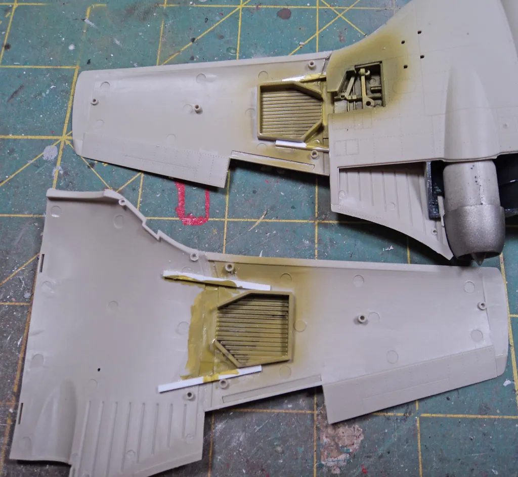
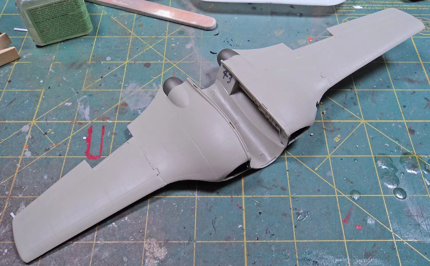
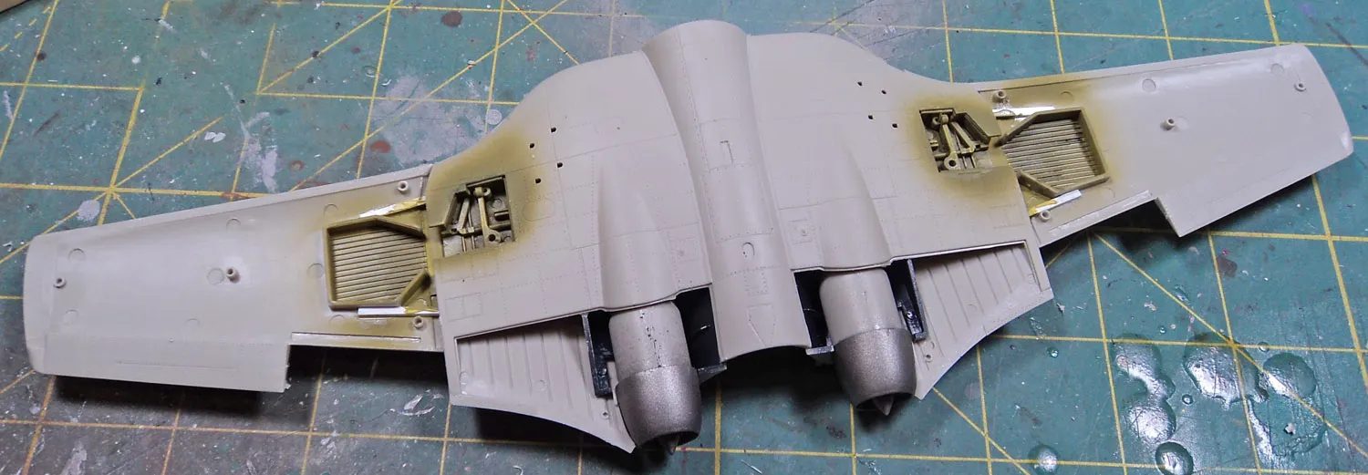
Having successfully navigated that area, I test fitted the wings to fuselage. I found it best to insert the aft half of the wings in first, with the front half angled down. Once the aft area was seated, I rotated the forward part up. It did require some firm force, but with a solid “pop”, it went into place. The system of grooves and tabs to help with the upper fuselage to wing join was perfect- absolutely perfect. There were some gaps fore and aft on the underside, but nothing onerous. Realizing the “test fit” was my “final fit”, I applied glue, and moved on.
The tailplanes went in place nicely.I then slotted the main gear in place, and tested how much nose weight I’d need. I used Liquid Gravity, and once I had enough in the gun bay (I did not install the guns!), a small amount of modeling clay was stuffed in to hold them in place, and the small nose cap was affixed.
In preparation for painting, I gave virtually all of the seams a treatment of Mr. Surfacer. In some areas all that was needed was to a cotton bud moistened with alcohol to clean things up. In others, light sanding was needed.
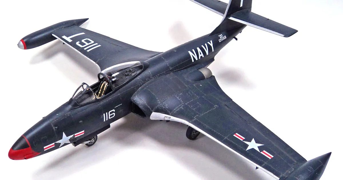
Tamiya Primer went on next, and then the painting. Because I used Model master Acryl- not my preferred paint by any stretch- for the dark blue, I painted all other colors first, masking them off as I went. (I had no faith in Acryl’s ability to stand up to masking…) Various places were hit with silver, read, and black, and then finally, the dark blue.
I did some very light post shading, and then a gloss coat for the decals.
Though I’d successfully gotten through the build of what was reported to be a tough kit, it was the decals that really flustered me. They were difficult to wrestle with. Once on, they looked fine and conformed well. But they were very matte, prone to silvering even over a gloss coat a car guy would be proud of, and folded easily. I’ve become so used to decals from Cartograph that I’ve become spoiled.
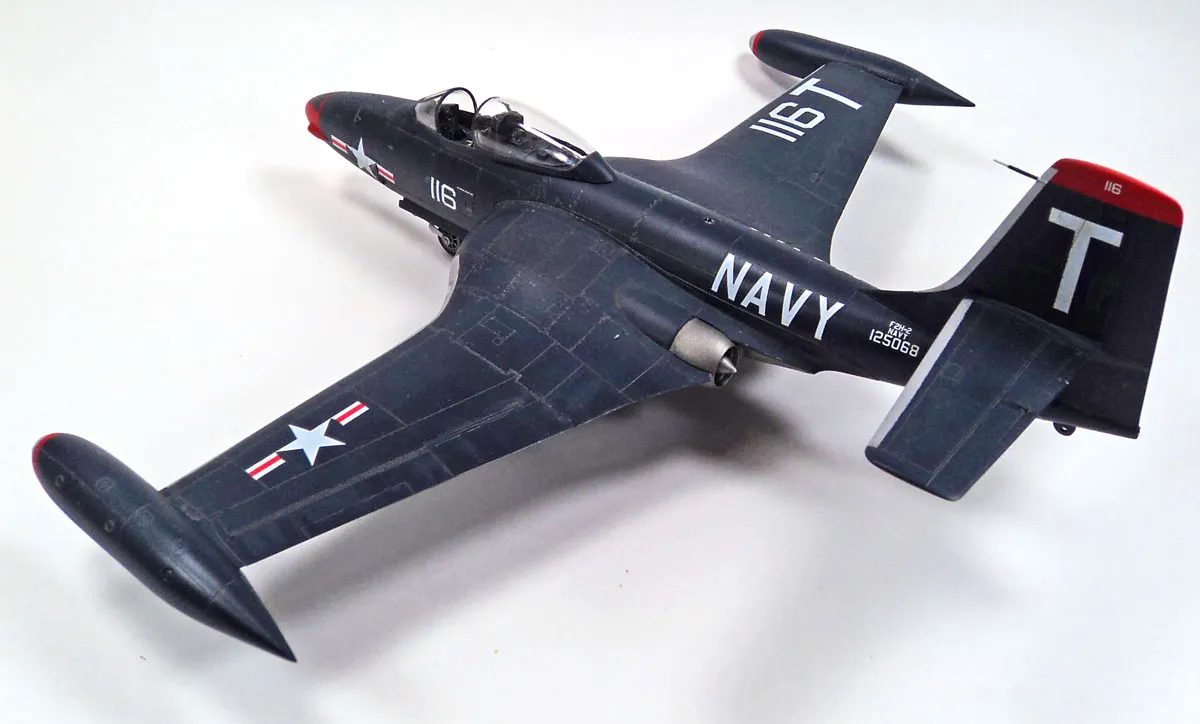
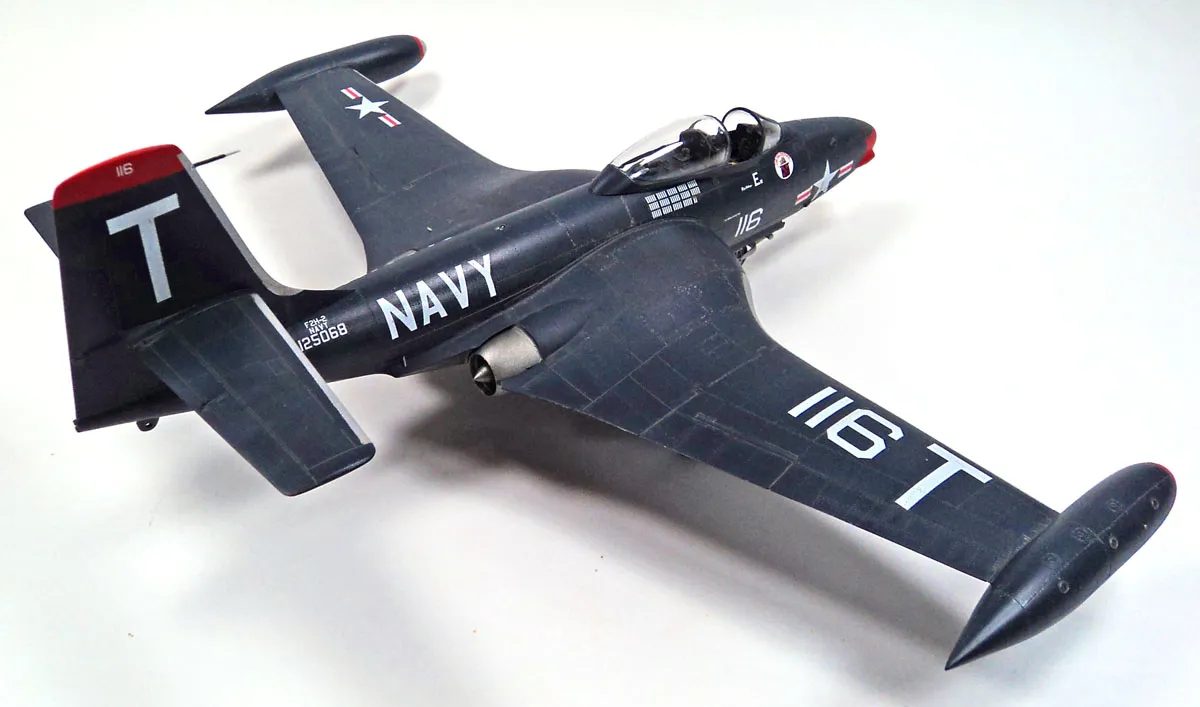
With those on, some more fading and shading was applied, a few streaks and stains, and some paint chipping. I set all the final parts on, and called this one finished.
While this is no Tamiya or Eduard kit, I can’t say that it was really difficult. Simply reading what others encountered, and taking appropriate steps to deal with them, made this a decidedly undramatic build.
I really enjoyed this one – please, KittyHawk, more of the same! (F2H-3/4, anyone?)



Leave a Reply